What is a carburettor?
A carburettor (American spelling), or carburetter (Commonwealth spelling) is a device that blends air and fuel for an internal combustion engine. It is sometimes shortened to carb in North America and the United Kingdom. Carburettors simply meter fuel inlet depending on the amount of air that is entering the engine. There are a couple problems though! Air and fuel have different viscosities, and since air and fuel do not flow the same, the metering of fuel is NOT LINEAR. What this means is that you can have a correct metering for a while, and then at certain RPMs (Revolutions Per Minute) it goes off. So, you have another set of jets to "correct" it and one more set to correct the correction.
Info from: http://en.wikipedia.org/wiki/Carburetor, and, http://www.aircooled.net/gnrlsite/resource/articles/jetting.htm
The first carburettors:
In 1885, Wilhelm Maybach and Gottlieb Daimler developed a carburettor for their engine based on the atomizer nozzle. The first carburettors were surface carburettors where the volatility of the petrol was utilized. A carburettor was among the early patents by Karl Benz as he developed internal combustion engines and their components. The Austrian automobile pioneer Siegfried Marcus invented the “rotating brush carburettor”. This was further improved by the Hungarian engineers János Csonka and Donát Bánki in 1893. Carburettors were the usual fuel delivery method for most U.S. made gasoline-fuelled engines up until the late 1980s, when fuel injection became the preferred method of automotive fuel delivery.
Venturi configurations:
Venturi-The reduction in fluid pressure that results when a fluid flows through a constricted section of pipe.
Fixed-venturi, in which the varying air velocity in the venturi alters the fuel flow; this system is installed in most carburettors found on cars.

Image from: http://www.motorera.com/dictionary/pics/c/carb.gif
Variable-venturi, in which the fuel jet opening is varied by the slide (which simultaneously alters air flow). In "constant depression" carburettors, this is done by a vacuum operated piston connected to a tapered needle which slides inside the fuel jet

Image from: http://www.powroll.com/images/img_tech/VARIABLE_VENTURI_CARB_DESIGN.gif
Info from: http://en.wikipedia.org/wiki/Carburetor
Components of a carburettor:


Images from: http://en.wikipedia.org/wiki/Carburetor
How the carburettor works:
For emissions and power, the engine has to have a certain amount of VAPORIZED fuel (liquid fuel doesn't burn) for a certain amount of air. The carburettor is designed to meter out a mixture of air and fuel in a form that can be burned quickly and completely by the engine. This is rarely done properly! For complete combustion, the air/fuel mixture must be supplied in a VAPOR, and not with liquid droplets (remember, liquid fuel won't burn). So, besides metering how much fuel the engine gets, the carburettor is also responsible to atomize the fuel and mix it with the air entering the engine.
Info from: http://www.aircooled.net/gnrlsite/resource/articles/jetting.htm
The carburettor works on Bernoulli's principle: the faster air moves, the lower its static pressure, and the higher its dynamic pressure. The throttle (accelerator) linkage does not directly control the flow of liquid fuel. Instead, it actuates carburettor mechanisms which meter the flow of air being pulled into the engine. The speed of this flow, and therefore its pressure, determines the amount of fuel drawn into the airstream. As shown in the animation below for a 2-Stroke bike engine:
Info from: http://en.wikipedia.org/wiki/Carburetor

Image from: http://calvinbayley.blogspot.com/
All 2 stroke engines use their crankcase similar to a supercharger to pack more air into the combustion chamber. First the engine draws air into the crankcase through whatever induction style they have. Then as the piston travels downward the air becomes pressurized and travels through air passages called transfer ports. These ports deliver fresh air to the upper part of the cylinder. Unfortunately the exhaust port is also open which leads to some fuel escaping out of the exhaust port. This is the real reason non direct injection two stroke engines smoke and have poor emissions.
Info from: http://www.freeengineinfo.com/two-stroke-induction-1.htm#more-164
The emulsion tube-What it is and how it works:
The air from the air bleeds enters the main circuit through the emulsion tube. The emulsion tube has a series of small holes from top to bottom, and it is through these holes that air enters the main circuit. At low engine speeds, when fuel demand is low, these holes are submerged in fuel, and so no air can flow through them. As engine speed increases, the fuel level in the float bowl drops, uncovering these holes, and allowing air from the bleeds to enter the main circuit, thus leaning the mixture. As the engine speed increases further, the fuel level in the float bowl continues to drop. This uncovers even more of the holes in the emulsion tube, which makes the air bleed have a greater effect on the mixture.
Info from: http://www.rhinoracing.com/yaw/carb_tuning.htm

Image from: http://www.prestonmoore.com/images/emulsion_tube.jpg
Chokes-What are they, and how do they work?
When the engine is cold, fuel vaporizes less readily and tends to condense on the walls of the intake manifold, starving the cylinders of fuel and making the engine difficult to start; thus, a richer mixture (more fuel to air) is required to start and run the engine until it warms up. A richer mixture is also easier to ignite.
A choke valve looks similar to the throttle valve and restricts the flow of air at the entrance to the carburettor, before the venturi. With this restriction in place, extra vacuum is developed in the carburettor barrel, which pulls extra fuel through the main metering system to supplement the fuel being pulled from the idle and off-idle circuits. This provides the rich mixture required to sustain operation at low engine temperatures.
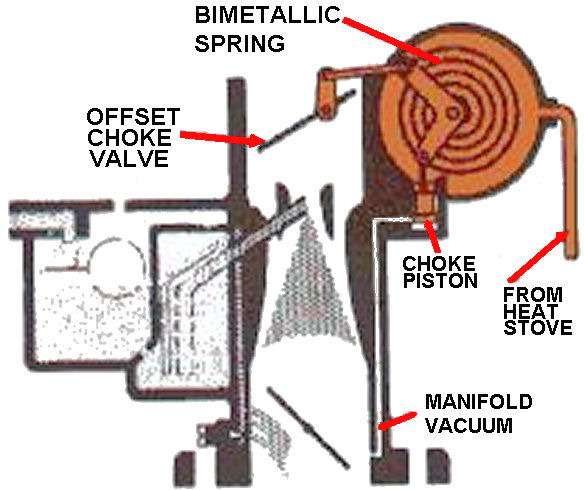
In many carburetted cars, the choke is controlled by a cable connected to a pull-knob on the dashboard operated by the driver (Manual choke). In some carburetted cars it is automatically controlled by a thermostat employing a bimetallic spring, which is exposed to engine heat, or to an electric heating element (Automatic choke). This heat may be transferred to the choke thermostat via simple convection, via engine coolant, or via air heated by the exhaust.
Info from: http://en.wikipedia.org/wiki/Carburetor
Types of chokes:
Automatic choke:
These can be operated in two ways:
1: by the heat of the cooling system or exhaust
2: by the heating effect of an electric current
These can either be:
Bimetal spring heated by heat from the cooling system or exhaust, or
Thermostatic 'wax start' which is also heated by the cooling system.
Operation:
In all cases when cold, the bimetal spring is tightly wound and holds the choke butterfly closed.
As the heat from the engine acts on the spring, either through the cooling system or exhaust, the spring gradually unwinds, opening the choke butterfly.
Info from: Applied technology & trades: Marine engineering systems book

Image from: http://www.motorera.com/dictionary/pics/a/achoke.jpg
Manual chokes:
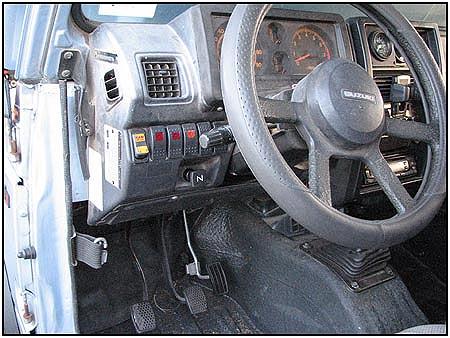
A manual choke has a cable/rod connected to the butterfly and attaches to a Pull-Knob in the interior of the vehicle, so the drive has to pull the knob out to close off the choke butterfly to start the engine(if cold) and push it back in again once the engine has started.

Image from: http://www.thebignic.com/vw/1641/manual-choke.JPG

Image from: http://www2.izook.com/images/1841.jpg
The “Float”-What it does and how it works
To ensure a ready mixture, the carburettor has a "float chamber" (or "bowl") that contains a quantity of fuel at near-atmospheric pressure, ready for use. This reservoir is constantly replenished with fuel supplied by a fuel pump. The correct fuel level in the bowl is maintained by means of a float controlling an inlet valve, in a manner very similar to that employed in a cistern (e.g. a toilet tank). As fuel is used up, the float drops, opening the inlet valve and admitting fuel. As the fuel level rises, the float rises and closes the inlet valve. The level of fuel maintained in the float bowl can usually be adjusted, whether by a setscrew or by something crude such as bending the arm to which the float is connected.
Info from: http://en.wikipedia.org/wiki/Carburetor

Image from: http://peswiki.com/images/0/07/Carburetor.jpg
Mechanical lift pumps-What they are, and how they work
A Mechanical pump lifts petrol at a pressure of between 2 and 5Psi (15-33Kpa) and is commonly operated by a lobe on the camshaft. As the operating lever is forced up by the lobe, the diaphragm is pulled down by the inner end of the lever, this increases the volume above the diaphragm dropping the pressure and allowing the inlet valve to open and fuel from the tank supply line to be drawn in. As the camshaft lobe turns further around, the diaphragm spring pushes the diaphragm upwards, pressurizing the fuel chamber.
If the float bowl level is low enough for the float needle valve to be open, the pump outlet valve will open and fuel will be forced into the carburettor float chamber. If the float bowl is full and the needle closed, the outlet valve still remains closed and te operating lever outer part will follow the cam lobe whilst the inner lever part remains in the down position.
As the float chamber level drops and fuel is forced past the pump outlet valve by the spring tension, the inner lever will slowly rise until the outer lever contacts it and pushes it down again drawing in more fuel. Keep in mind that the spring tension that controls the pump pressure. If the spring is too strong, it will overcome the float needle and cause flooding. If the spring is too weak, the fuel will not be moved at the right force to keep the float chamber full causing fuel starvation.
Info from: Applied Technology & Trades-Marine Engineering Systems book

Image from: http://indoblogger.org/wp-content/uploads/2010/08/How-mechanical-pump-works.jpg
Excellent work, although it would be easier if each subject was just one entry as opposed to many.
ReplyDelete