Tuesday, May 31, 2011

Fuel Injection

What IS fuel injection?

Fuel injection is a system for mixing fuel with air in an internal combustion engine. It has become the primary fuel delivery system used in automotive engines, having almost completely replaced carburettors in the late 1980s.

Jeep_2.5_liter_4-cylinder_engine_chromed_i

Image from: http://upload.wikimedia.org/wikipedia/commons/f/f8/Jeep_2.5_liter_4-cylinder_engine_chromed_i.jpg

Info from: http://en.wikipedia.org/wiki/Fuel_injection

Who Invented fuel injection and when?

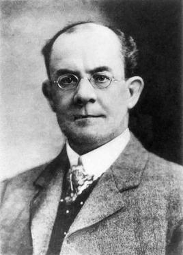
Herbert Akroyd Stuart developed the first system laid out on modern lines (with a highly-accurate 'jerk pump' to meter out fuel oil at high pressure to an injector. This system was used on the hot bulb engine and was adapted and improved by Robert Bosch for use on diesel engines.

Herbert_Akroyd_Stuart

Image of Herbert Akroyd Stuart found at: http://upload.wikimedia.org/wikipedia/en/2/29/Herbert_Akroyd_Stuart.jpg

The first use of direct gasoline injection was on the Hesselman engine invented by Swedish engineer Jonas Hesselman in 1925.

Info from: http://en.wikipedia.org/wiki/Fuel_injection#History_and_development

The Hesselman engine is a hybrid between a petrol engine and a Diesel engine.

Hesselman engine

Image from: http://cdn.dipity.com/uploads/events/f575514d4740ff705203078f0595fa0e_1M.png

Info from: http://en.wikipedia.org/wiki/Hesselman_engine

What does EFI stand for?

EFI stands for: Electronic fuel injection, internal combustion engine technology.

Info from: http://en.wikipedia.org/wiki/EFI#Technology

What is an ECU and how does it work?

An engine control unit (ECU), also known as power-train control module (PCM), or engine control module (ECM) is a type of electronic control unit that determines the amount of fuel, ignition timing and other parameters an internal combustion engine needs to keep running. It does this by reading values from multidimensional performance maps (so called LUTs), using input values (e.g. engine speed) calculated from signals coming from sensor devices monitoring the engine. Before ECU's, air/fuel mixture, ignition timing, and idle speed were directly controlled by mechanical and pneumatic sensors and actuators.

Info from: http://en.wikipedia.org/wiki/Engine_control_unit

ECU

Image from: http://www.team-integra.net/images/BAEC1978-D3A7-4405-AB2D-2761DC15A96D/articles/tuan/p73A0ECU-retry.jpg

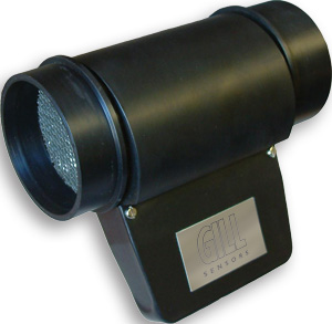
Mass Air Flow Sensor-What it is and how it works

A mass air flow sensor is used to find out the mass of air entering a fuel-injected internal combustion engine. The air mass information is necessary for the engine control unit (ECU) to balance and deliver the correct fuel mass to the engine. Air changes its density as it expands and contracts with temperature and pressure. In automotive applications, air density varies with the ambient temperature, altitude and use of forced induction and this is an ideal application for a mass sensor.

Info from: http://en.wikipedia.org/wiki/Mass_flow_sensor

Mass-airflow

Image from: http://upload.wikimedia.org/wikipedia/commons/e/e8/Mass-airflow.jpg

Air Tem Sensor:

An air temperature sensor is used on fuel injected engines. The purpose of an air temperature sensor is to help the computer calculate air density. A change in temperature changes the resistance in the sensor. Simply stated, the higher the air temperature gets the less dense the air becomes. As the air becomes less dense the computer knows that it needs to lessen the fuel flow. If the fuel flow was not changed the engine would become rich, possibly losing power and consuming more fuel.

air temp sensor

Info and image  from: http://www.freeengineinfo.com/air-temp-sensor.htm

Throttle Position Switch-What it is and how it works:

A throttle position sensor (TPS) is a sensor used to monitor the position of the throttle in an internal combustion engine. The sensor is usually located on the butterfly spindle so that it can directly monitor the position of the throttle valve butterfly. The senor is usually a potentiometer, and therefore provides a variable resistance dependent upon the position of the valve (and hence throttle position).

The sensor signal is used by the engine control unit (ECU) as an input to its control system. The ignition timing and fuel injection timing (and potentially other parameters) are altered depending upon the position of the throttle, and also depending on the rate of change of that position. For example, in fuel injected engines, in order to avoid stalling, extra fuel may be injected if the throttle is opened rapidly (mimicking the accelerator pump of carburettor systems).

Info from: http://en.wikipedia.org/wiki/Throttle_position_sensor

throttlesensors

Image from: http://moodle.student.cnwl.ac.uk/moodledata_shared/CDX%20eTextbook/dswmedia/images/throttlesensors.jpg
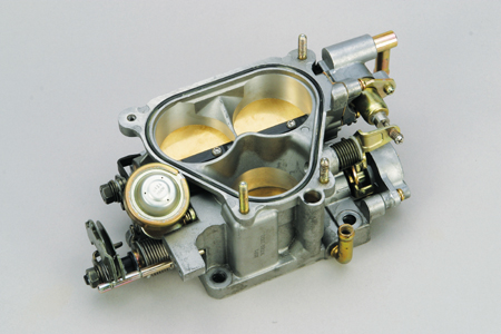
Throttle body:

A throttle is the mechanism by which the flow of a fluid is managed by constriction or obstruction. An engine's power can be increased or decreased by the restriction of inlet gases (i.e., by the use of a throttle), but usually decreased. The term throttle has come to refer, informally and incorrectly, to any mechanism by which the power or speed of an engine is regulated.

Info from: http://en.wikipedia.org/wiki/Throttle

nengun-1620-02-fujitaengineering-throttle_body

Image from: http://image.nengun.com/catalogue/original/nengun-1620-02-fujitaengineering-throttle_body.jpg

The temperature sensor

An ECT sensor, or Engine Coolant Temperature Sensor is a sensor that is screwed into the engine's block or cylinder head and is used to determine the temperature of the engine coolant. The ECT sensor is basically a thermistor that changes resistance with temperature. When the ECT (engine coolant temperature) is high (hotter), the resistence is low, and when the ECT is low (cooler) the resistence is high. This resistance reading is sent to the vehicle's PCM/ECM (car's onboard computer) and is or can be used to activate emission controls or turn the engine's cooling fan on.

Info form: http://www.obd-codes.com/faq/ect-sensor.php

 ect-sensor

Image from: http://www.obd-codes.com/faq/ect-sensor.php

Fuel Rail:

A fuel rail is essentially a pipe (usually resembling a rail) used to deliver fuel to individual fuel injectors on internal combustion engines. It is designed to have a pocket or seat for each injector as well as an inlet for a fuel supply. Some fuel rails also incorporate an attached fuel pressure regulator. Fuel rails are used on engines with multi-point fuel injection systems, although some multi-point systems use a fuel distributor with individual pipes or tubes to feed each injector.

Info from: http://en.wikipedia.org/wiki/Fuel_rail

Fuel_rail

Image from: http://upload.wikimedia.org/wikipedia/en/f/f4/Fuel_rail.JPG

Fuel pressure regulator:

The installation of an aftermarket fuel pressure regulator allows for the adjustment of fuel pressure to suit larger aftermarket injectors and other engine modifications. They are also necessary to regulate and flow increased volumes of fuel pumped by high flow aftermarket fuel pumps. Fuel pressure regulators work with the fuel pump to maintain a steady pressure relationship between the fuel line side of the injectors and the intake manifold.

Info from: http://www.xspeed.com.au/tech_features.php?tech_id=24

fuel pressure regulator

Image from: http://www.mvagusta.net/forum/attachment.php?attachmentid=44031&stc=1&d=1299150472
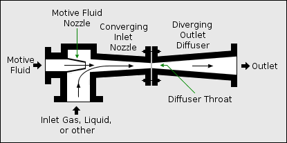
Injectors:

An injector, ejector, steam ejector, steam injector, eductor-jet pump or thermo-compressor is a pump-like device that uses the Venturi effect of a converging-diverging nozzle to convert the pressure energy of a motive fluid to velocity energy which creates a low pressure zone that draws in and entrains a suction fluid.

Info from: http://en.wikipedia.org/wiki/Injector

converging-diverging nozzle- A convergent-divergent nozzle,  is a tube that is pinched in the middle, making a carefully balanced, asymmetric hourglass-shape. It is used to accelerate a hot, pressurised gas passing through it to a supersonic speed, and upon expansion, to shape the exhaust flow so that the heat energy propelling the flow is maximally converted into directed kinetic energy.

Info from: http://en.wikipedia.org/wiki/De_Laval_nozzle

Ejector_or_Injector

Image from: http://upload.wikimedia.org/wikipedia/commons/b/b4/Ejector_or_Injector.png

Idle Air Control:

An IAC (idle air control) motor is designed to adjust the engine idle RPM speed by opening and closing an air bypass passage inside the throttle body. The cars computer or PCM (power train control module) receives information from various sensors and will output signals to adjust the idle air control motor in or out to adjust engine idle speed by controlling engine idle air.

Info from: http://www.2carpros.com/articles/how-a-idle-air-control-valve-works

IAC

Image from: http://www.2carpros.com/articles/how-a-idle-air-control-valve-works

Oxygen sensor:

An oxygen sensor, or lambda sensor, is an electronic device that measures the proportion of oxygen (O2) in the gas or liquid being analyzed. Lambda probes are used to reduce vehicle emissions by ensuring that engines burn their fuel efficiently and cleanly. The zirconium dioxide, or zirconia, lambda sensor is based on a solid-state electrochemical fuel cell called the Nernst cell. Its two electrodes provide an output voltage corresponding to the quantity of oxygen in the exhaust relative to that in the atmosphere. (e.g. An output voltage of 0.2 V (200 mV) DC represents a "lean mixture" of fuel and oxygen and An output voltage of 0.8 V (800 mV) DC represents a "rich mixture".

Info from: http://en.wikipedia.org/wiki/Oxygen_sensor

o2-sensors

Image from: http://cf.blogetery.com/65254/files/2010/01/o2-sensors.jpg

MAP Sensor:

The Manifold Absolute Pressure sensor (MAP sensor) is one of the sensors used in an internal combustion engine's electronic control system. Engines that use a MAP sensor are typically fuel injected. The manifold absolute pressure sensor provides instantaneous manifold pressure information to the engine's electronic control unit (ECU). The data is used to calculate air density and determine the engine's air mass flow rate, which in turn determines the required fuel metering for optimum combustion.

Info from: http://en.wikipedia.org/wiki/MAP_sensor

map

Image from: http://journal.alone.cl/wp-content/uploads/2010/06/map.jpg

Plenum chamber:

A plenum chamber is a pressurised housing containing a gas or fluid (typically air) at positive pressure (pressure higher than surroundings). One function of the plenum can be to equalise pressure for more even distribution, because of irregular supply or demand. A plenum chamber can also work as an acoustic silencer device.

Info from: http://en.wikipedia.org/wiki/Plenum_chamber

Plenum chamber

Image from: http://www.professional-products.com/images/manifold/Imports/honda59000b.jpg

Crank & Camshaft sensors:

Crank sensors in engines usually consist of magnets and an inductive coil, or they may be based on magnetically triggered Hall effect semiconductor devices. Common mounting locations include the main crank pulley, the flywheel, and occasionally on the crankshaft itself. This sensor is the most important sensor in modern day engines. The crank sensor can be used in combination with a similar camshaft position sensor to monitor the relationship between the pistons and valves in the engine, which is particularly important in engines with variable valve timing. It is also commonly the primary source for the measurement of engine speed in revolutions per minute.

Info from: http://en.wikipedia.org/wiki/Crank_sensor

crank_sensor copy

Image from: http://www.automotivetroubleshootingsecrets.com/crank_sensor%20copy.jpg

camshaft_position_sensor

Image from: http://www.auto-repair-help.com/images/articles/articles_0808/camshaft_position_sensor.jpg

Monday, May 30, 2011

Fuel injection questions

Need to find out the purpose and how they work for each of the components below:
ECU- Electronic control unit?
Mass air flow sensor?
Air Temp sensor?
TPS throttle position sensor?
Throttle body?
Temp sensor?
fuel rail?
Fuel pressure regulator?
Injectors?
Idle air control?
O2 sensor ( lambda sensor)?
Map sensor?
Plenum chamber?
Camshaft & Crankshaft sensor?
Who invented fuel injection and when?
Explain how an single and mutli injection system works?
What does EFI stand for?

Carburettors continued

What is the difference between petrol and diesel fuel?
How does the fuel shut off solenoid work?
What is the four stroke cycle?
What does S.I mean?
What does C.I mean?
When dismantling a carb what precaution should you take?
How does a bimetallic spring work in a automatic choke?
What is the purpose of the venturi and how does it work?
Explain how a fuel cut off solenoid is checked and why is it fitted?
An engine lacks power. What is likely to cause this problem?
How do you adjust the float in a carburettor?
What is the purpose of a power valve?
What are some of the causes of high fuel consumption?
How is the the idle and mixture screw adjusted?
When refitting a three multiple carburettor what should be done after installing them?

Petrol:

Petroleum is a mixture of a very large number of different hydrocarbons; the most commonly found molecules are alkanes (linear or branched), cycloalkanes, aromatic hydrocarbons, or more complicated chemicals like asphaltenes. Each petroleum variety has a unique mix of molecules, which define its physical and chemical properties, like colour and viscosity.

  Petrol

Image from: http://images.cdn.fotopedia.com/flickr-2889488104-image.jpg

Hydrocarbon- A Hydrocarbon is an organic compound consisting entirely of hydrogen and carbon.

Hydrocarbon

Image from: http://www.lloydminsterheavyoil.com/propane.jpg

Alkanes- Alkanes (also known as paraffins or saturated hydrocarbons) are chemical compounds that consist only of the elements carbon (C) and hydrogen (H)

Alkayne structure

Image from: http://www.jirvine.co.uk/Chemistry_GCSE/C1A/methane.JPG

Cycloalkanes- Cycloalkanes (also called naphthenes) are types of alkanes which have one or more rings of carbon atoms in the chemical structure of their molecules.

220px-Cyclobutane-buckled-3D-balls

Image from: http://upload.wikimedia.org/wikipedia/commons/thumb/0/0e/Cyclobutane-buckled-3D-balls.png/220px-Cyclobutane-buckled-3D-balls.png

Aromatic hydrocarbon- An Aromatic hydrocarbon or arene is a hydrocarbon characterized by general alternating double and single bonds between carbons.

135869main_panha

Image from: http://www.nasa.gov/centers/ames/images/content/135869main_panha.jpg

Asphaltenes- Asphaltenes are molecular substances that are found in crude oil, along with resins, aromatic hydrocarbons, and alkanes.

Asphaltene.Aggregation

Image from: http://tigger.uic.edu/~mansoori/Asphaltene.Aggregation.GIF

Info from: http://en.wikipedia.org/wiki/Petroleum#Chemistry, http://en.wikipedia.org/wiki/Hydrocarbon, http://en.wikipedia.org/wiki/Alkane, http://en.wikipedia.org/wiki/Cycloalkane, http://en.wikipedia.org/wiki/Aromatic_hydrocarbon, http://en.wikipedia.org/wiki/Asphaltene

Diesel:

Diesel fuel in general is any liquid fuel used in diesel engines. The most common is a specific fractional distillate of petroleum fuel oil, but alternatives that are not derived from petroleum, such as biodiesel, biomass to liquid (BTL) or gas to liquid (GTL) diesel, are increasingly being developed and adopted Petroleum-derived diesel is composed of about 75% saturated hydrocarbons (primarily paraffins including, cycloparaffins), and 25% aromatic hydrocarbons (including naphthalenes and alkylbenzenes).

diesel-2

Image from: http://static.howstuffworks.com/gif/diesel-2.jpg

Fractional Distillation- Fractional distillation is the separation of a mixture into its component parts, or fractions, such as in separating chemical compounds by their boiling point by heating them to a temperature at which several fractions of the compound will evaporate.

FRACTIONAL DISTILLATION

Image from: http://www.tutorbene.com/cms_images/FRACTIONAL%20DISTILLATION.bmp

Biodiesel- Biodiesel refers to a vegetable oil- or animal fat-based diesel fuel typically made by chemically reacting lipids (e.g., vegetable oil, animal fat (tallow) with an alcohol.

re_biodiesel_carboncycle

Image from: http://www.seco.cpa.state.tx.us/zzz_re/re_biodiesel_carboncycle.gif

Paraffin- In chemistry, paraffin is a term that can be used synonymously with "alkane", indicating hydrocarbons with the general formula CnH2n+2.

Pure_Liquid_Paraffin

Image from: http://lembex-import-inc.tradenote.net/images/users/000/201/938/products_images/Pure_Liquid_Paraffin.jpg

Naphthalene- Naphthalene is an organic compound with formula C10H8.

Naphthalene-3D-balls

Image from: http://upload.wikimedia.org/wikipedia/commons/3/3e/Naphthalene-3D-balls.png

Benzene- Benzene is an organic chemical compound with the molecular formula C6H6. It is sometimes abbreviated Ph–H. Benzene is a colourless and highly flammable liquid with a sweet smell.

benzene

Image from: http://zoxovema.comlu.com/gallery/benzene.jpg

Info from: http://en.wikipedia.org/wiki/Diesel_fuel#Chemical_composition, http://en.wikipedia.org/wiki/Paraffin, http://en.wikipedia.org/wiki/Naphthalene, http://en.wikipedia.org/wiki/Alkylbenzene\, http://en.wikipedia.org/wiki/Fractional_distillation

The 4-Stroke cycle:

4-Stroke cycle animation found on YouTube-

S.I engine:

Spark Ignition engine- Petrol operating engine

Video found on you tube

C.I engine:

Compression Ignition engine- Diesel operating engine

Video found on You Tube

Fuel shutoff solenoid-why it’s fitted, how it works, and how it’s checked

A solenoid valve is an electromechanical valve controlled by an electric current. The electric current runs through a solenoid, which is a wire coil wrapped around a metallic core. A solenoid creates a controlled magnetic field when an electrical current is passed through it. This magnetic field affects the state of the solenoid valve, causing the valve to open or close. Fuel shut-off solenoids transport fuel from a machine's gas tank to its engine. A fuel shut-off solenoid is attached to the machine's main electrical system, which can monitor and detect abnormal temperatures or mechanical malfunctions. Should something go wrong, the electrical current running to the solenoid will be interrupted, causing the solenoid valve to close and shutting off the supply of fuel to the engine.

Info from: http://www.ehow.com/how-does_5016171_diesel-fuel-shutoff-solenoids-work.html

Fuel cutoff solenoid 

Image from: http://cf.mp-cdn.net/63/2e/3f2e8ffd3cf6050ab42cec2cf7f1.jpg

The venturi-The purpose and how it works

When air is drawn down a tube that has a restriction in it like the throat and venturi in the diaphragm, it must speed up as it passes the restriction. As it does so the pressure in the area of the restriction or venturi drops. This drop in pressure is used to draw fuel into the throat of the carburettor. There must be  a constant supply of fuel with a level slightly bellow the opening of the discharge tube or nozzle into the venturi. To achieve this, a float chamber is used in which a float and needle valve provide a constant fuel level within the chamber.

Info from: Applied technology & trades-Marine engineering book

Video found on YouTube explaining the venturi effect-

Power valve-It’s purpose

For open throttle operation a richer mixture will produce more power, prevent pre-ignition detonation, and keep the engine cooler. This is usually addressed with a spring-loaded "power valve", which is held shut by engine vacuum. As the throttle opens up, the vacuum decreases and the spring opens the valve to let more fuel into the main circuit. On two-stroke engines, the operation of the power valve is the reverse of normal — it is normally "on" and at a set rpm it is turned "off". It is activated at high rpm to extend the engine's rev range, capitalizing on a two-stroke's tendency to rev higher momentarily when the mixture is lean.

ashima-power-valve-brake

Image from: http://www.bikerumor.com/wp-content/uploads/2009/07/ashima-power-valve-brake.jpg

Info from: http://en.wikipedia.org/wiki/Carburetor#Power_valve

When dismantling  a carburettor, you should be aware of small components such as: needle valves used to  block and allow fuel/air flow, ball Barings used to allow fuel/air flow. Basically, when taking a carburettor apart, keep components in their assigned group. E.g. When unscrewing bolts from the float bowl/chamber, lie them down in which hole they came out of (e.g: if bolts came from holes on the left of the float bowl, put them next to you in order from top to bottom. Visa versa for opposite side). keep a magnetic pick up close by. If you drop a piece and lose it, buy a new carburettor. You can’t afford to lose a single component/piece of carburettor when taking apart of fixing them. It could result in high fuel consumption and/or cause the engine to run lean or too rich. It is vital not to lose the component on a carburettor, such as the components pointed out bellow.

OgAAADQ4OYsNxsupIjCM1bABr1NUVzUyxqFvhqqt7ZAD8gsj8A9DU68iUFUvBZuCDI-7RGfWYooV7f932GSzDLUsY2QA15jOjFsu1zwPPOxX-jWNw8ScHAQUixcM

Image from: https://docs.google.com/present/view?id=df8cgkbk_88cgrtb2fz

Info from my knowledge of carburettor dismantling.

Carburettor problems:

The reasons why an engine lacks power would be that:

. The power valve is stuck closed, or

. The float level is too low, or

. There are restrictions in jets, air bleeds, or passage ways, or

. There is lack of fuel to the carburettor, or

. The air intake has restrictions, or

. The inlet manifold has leaks, or

. The secondary butterfly is not opening properly (dual throat carb), or

. The accelerator cable is not adjusted properly or has faults, or

. The secondary secondary air valve isn't opening properly (dual throat carb).

Info from: Page 9 of TTEC 4234 Fuels and fuel systems-Marine (Fuels practical workbook) book

Alternate causes of high fuel consumption are:

. The choke valve isn’t opening/open properly, or

. The carburettor is flooding, or

. The float level is too high, or

. There is fuel percolation (percolation- concerns the movement and filtering of fluids through porous materials in the bowl), or

Info from: http://en.wikipedia.org/wiki/Percolation

. The air being sucked into the air intake is either too hot or too cold, or

. The air intake has restrictions, or

. The fuel line and/or fittings have leaks, or

. The power valve is stuck open, or

. The link to the accelerator pump is out of adjustment, or

. There are restrictions in the air bleeds or passages.

Info from: Page 11 of TTEC 4234 Fuels and fuel systems-Marine (Fuels practical workbook) book

Adjustment of the idle mixture screw:

The idle and mixture screws are adjusted by either a Philips or flathead screw driver. (Screw heads vary depending on carburettor model).

Info from my knowledge of dismantling carburettors

How the vacuum fuel pump works:

Since the carburettor isn’t manly enough to suck enough fuel into the top of the cylinder head(s), a vacuum pump is fitted in/onto the fuel system. the vacuum pump consists of a diaphragm which uses the stroke/pressure of the pistons to suck fuel into the carb and into the top of the cylinder heads. The pressure you would get from this type of pump would be around 30 to 80 psi of fuel pressure.

vro719x632

Image from: http://continuouswave.com/whaler/reference/images/vro719x632.jpg

Info (edited) from:  http://gregtothill.blogspot.com/, http://calvinbayley.blogspot.com/, and http://www.aa1car.com/library/fuel_pump_diagnose.htm

Friday, May 27, 2011

Update

Well… The marine and automotive students were combined earlier this week and we were doing some engine diagnostics.
After a failed engine start, I decided to walk round the work shop.

So, while we had our engine running... Calvin had a bit of trouble getting our Oscilloscope adjusted.

The next day, we were doing some checks on Sanji's car. What was supposed to be a 'slight' leak, turned out to be a MAJOR air leak in the intake manifold and his car was sucking too much air in causing the engine to idle like a piece of SH**! So, Steve (our reliever) got Niel to hold a tube to his ear so that he could have two hands free to find out where the leak was.
ROFL!


The next day, Rob recovered from his sickness and came with his Scan tool so we could do further inspections on Sanji's car.
Rob, (right) had the Scan too all connected and told us all the cool things that it can see on the engine

 After a few demonstrations on what this tool can actually do, He let us have a go, so Niel took tha opportunity.

Tuesday, May 24, 2011

Carburettors

What is a carburettor?

A carburettor (American spelling), or carburetter (Commonwealth spelling) is a device that blends air and fuel for an internal combustion engine. It is sometimes shortened to carb in North America and the United Kingdom. Carburettors simply meter fuel inlet depending on the amount of air that is entering the engine. There are a couple problems though! Air and fuel have different viscosities, and since air and fuel do not flow the same, the metering of fuel is NOT LINEAR. What this means is that you can have a correct metering for a while, and then at certain RPMs (Revolutions Per Minute) it goes off. So, you have another set of jets to "correct" it and one more set to correct the correction.

Info from: http://en.wikipedia.org/wiki/Carburetor, and, http://www.aircooled.net/gnrlsite/resource/articles/jetting.htm

The first carburettors:

In 1885, Wilhelm Maybach and Gottlieb Daimler developed a carburettor for their engine based on the atomizer nozzle. The first carburettors were surface carburettors where the volatility of the petrol was utilized. A carburettor was among the early patents by Karl Benz as he developed internal combustion engines and their components. The Austrian automobile pioneer Siegfried Marcus invented the “rotating brush carburettor”. This was further improved by the Hungarian engineers János Csonka and Donát Bánki in 1893. Carburettors were the usual fuel delivery method for most U.S. made gasoline-fuelled engines up until the late 1980s, when fuel injection became the preferred method of automotive fuel delivery.

Venturi configurations:

Venturi-The reduction in fluid pressure that results when a fluid flows through a constricted section of pipe.

Fixed-venturi, in which the varying air velocity in the venturi alters the fuel flow; this system is installed in most carburettors found on cars.

carb

Image from: http://www.motorera.com/dictionary/pics/c/carb.gif

Variable-venturi, in which the fuel jet opening is varied by the slide (which simultaneously alters air flow). In "constant depression" carburettors, this is done by a vacuum operated piston connected to a tapered needle which slides inside the fuel jet

VARIABLE_VENTURI_CARB_DESIGN

Image from: http://www.powroll.com/images/img_tech/VARIABLE_VENTURI_CARB_DESIGN.gif

Info from: http://en.wikipedia.org/wiki/Carburetor

Components of a carburettor:

Annotated_rude_carb 

639px-Carburetor.svg

Images from: http://en.wikipedia.org/wiki/Carburetor

How the carburettor works:

For emissions and power, the engine has to have a certain amount of VAPORIZED fuel (liquid fuel doesn't burn) for a certain amount of air. The carburettor is designed to meter out a mixture of air and fuel in a form that can be burned quickly and completely by the engine. This is rarely done properly! For complete combustion, the air/fuel mixture must be supplied in a VAPOR, and not with liquid droplets (remember, liquid fuel won't burn). So, besides metering how much fuel the engine gets, the carburettor is also responsible to atomize the fuel and mix it with the air entering the engine.

Info from: http://www.aircooled.net/gnrlsite/resource/articles/jetting.htm

The carburettor works on Bernoulli's principle: the faster air moves, the lower its static pressure, and the higher its dynamic pressure. The throttle (accelerator) linkage does not directly control the flow of liquid fuel. Instead, it actuates carburettor mechanisms which meter the flow of air being pulled into the engine. The speed of this flow, and therefore its pressure, determines the amount of fuel drawn into the airstream. As shown in the animation below for a 2-Stroke bike engine:

Info from: http://en.wikipedia.org/wiki/Carburetor

Arbeitsweise_Zweitakt

Image from: http://calvinbayley.blogspot.com/

All 2 stroke engines use their crankcase similar to a supercharger to pack more air into the combustion chamber. First the engine draws air into the crankcase through whatever induction style they have. Then as the piston travels downward the air becomes pressurized and travels through air passages called transfer ports. These ports deliver fresh air to the upper part of the cylinder. Unfortunately the exhaust port is also open which leads to some fuel escaping out of the exhaust port. This is the real reason non direct injection two stroke engines smoke and have poor emissions.

Info from: http://www.freeengineinfo.com/two-stroke-induction-1.htm#more-164

The emulsion tube-What it is and how it works:

The air from the air bleeds enters the main circuit through the emulsion tube. The emulsion tube has a series of small holes from top to bottom, and it is through these holes that air enters the main circuit. At low engine speeds, when fuel demand is low, these holes are submerged in fuel, and so no air can flow through them. As engine speed increases, the fuel level in the float bowl drops, uncovering these holes, and allowing air from the bleeds to enter the main circuit, thus leaning the mixture. As the engine speed increases further, the fuel level in the float bowl continues to drop. This uncovers even more of the holes in the emulsion tube, which makes the air bleed have a greater effect on the mixture.

Info from: http://www.rhinoracing.com/yaw/carb_tuning.htm

emulsion_tube

Image from: http://www.prestonmoore.com/images/emulsion_tube.jpg

Chokes-What are they, and how do they work?

When the engine is cold, fuel vaporizes less readily and tends to condense on the walls of the intake manifold, starving the cylinders of fuel and making the engine difficult to start; thus, a richer mixture (more fuel to air) is required to start and run the engine until it warms up. A richer mixture is also easier to ignite.

A choke valve looks similar to the throttle valve and restricts the flow of air at the entrance to the carburettor, before the venturi. With this restriction in place, extra vacuum is developed in the carburettor barrel, which pulls extra fuel through the main metering system to supplement the fuel being pulled from the idle and off-idle circuits. This provides the rich mixture required to sustain operation at low engine temperatures.

In many carburetted cars, the choke is controlled by a cable connected to a pull-knob on the dashboard operated by the driver (Manual choke). In some carburetted cars it is automatically controlled by a thermostat employing a bimetallic spring, which is exposed to engine heat, or to an electric heating element (Automatic choke). This heat may be transferred to the choke thermostat via simple convection, via engine coolant, or via air heated by the exhaust.

Info from: http://en.wikipedia.org/wiki/Carburetor

Types of chokes:

Automatic choke:
These can be operated in two ways:
1: by the heat of the cooling system or exhaust
2: by the heating effect of an electric current
These can either be:
Bimetal spring heated by heat from the cooling system or exhaust, or
Thermostatic 'wax start' which is also heated by the cooling system.

Operation:
In all cases when cold, the bimetal spring is tightly wound and holds the choke butterfly closed.
As the heat from the engine acts on the spring, either through the cooling system or exhaust, the spring gradually unwinds, opening the choke butterfly.

Info from: Applied technology & trades: Marine engineering systems book

  achoke

Image from: http://www.motorera.com/dictionary/pics/a/achoke.jpg

Manual chokes:
A manual choke has a cable/rod connected to the butterfly and attaches to a Pull-Knob in the interior of the vehicle, so the drive has to pull the knob out to close off the choke butterfly to start the engine(if cold) and push it back in again once the engine has started.

manual-choke 

Image from: http://www.thebignic.com/vw/1641/manual-choke.JPG

1841

Image from: http://www2.izook.com/images/1841.jpg

The “Float”-What it does and how it works

To ensure a ready mixture, the carburettor has a "float chamber" (or "bowl") that contains a quantity of fuel at near-atmospheric pressure, ready for use. This reservoir is constantly replenished with fuel supplied by a fuel pump. The correct fuel level in the bowl is maintained by means of a float controlling an inlet valve, in a manner very similar to that employed in a cistern (e.g. a toilet tank). As fuel is used up, the float drops, opening the inlet valve and admitting fuel. As the fuel level rises, the float rises and closes the inlet valve. The level of fuel maintained in the float bowl can usually be adjusted, whether by a setscrew or by something crude such as bending the arm to which the float is connected.

Info from: http://en.wikipedia.org/wiki/Carburetor

Carburetor

Image from: http://peswiki.com/images/0/07/Carburetor.jpg

Mechanical lift pumps-What they are,  and how they work

A Mechanical pump lifts petrol at a pressure of between 2 and 5Psi (15-33Kpa) and is commonly operated by a lobe on the camshaft. As the operating lever is forced up by the lobe, the diaphragm is pulled down by the inner end of the lever, this increases the volume above the diaphragm dropping the pressure and allowing the inlet valve to open and fuel from the tank supply line to be drawn in. As the camshaft lobe turns further around, the diaphragm spring pushes the diaphragm upwards, pressurizing the fuel chamber.

If the float bowl level is low enough for the float needle valve to be open, the pump outlet valve will open and fuel will be forced into the carburettor float chamber. If the float bowl is full and the needle closed, the outlet valve still remains closed and te operating lever outer part will follow the cam lobe whilst the inner lever part remains in the down position.

As the float chamber level drops and fuel is forced past the pump outlet valve by the spring tension, the inner lever will slowly rise until the outer lever contacts it and pushes it down again drawing in more fuel. Keep in mind that the spring tension that controls the pump pressure. If the spring is too strong, it will overcome the float needle and cause flooding. If the spring is too weak, the fuel will not be moved at the right force to keep the float chamber full causing fuel starvation.

Info from: Applied Technology & Trades-Marine Engineering Systems book

How-mechanical-pump-works

Image from: http://indoblogger.org/wp-content/uploads/2010/08/How-mechanical-pump-works.jpg